
Industrial Fibre Optic Communications
Fibre optics are long, thin strands of very pure glass – about the diameter of a human hair. They carry much more information than conventional copper wire and are completely immune to electromagnetic interference (EMI).
Why Fibre for Industrial Environments
Fibre optic cables are ideal for harsh industrial installations. They provide reliable transmission and high data transfer capacity over long distances. Almost all telephone long-distance lines are fibre optic cables.
Advantages of fibre optic cables over copper wire are substantial. Speed operates at high data rates – up into the gigabits. Bandwidth provides large data carrying capacity. Distance reaches longer ranges without needing amplification or boosting. Immunity to electromagnetic interference (EMI) is complete – a critical advantage in environments with variable speed drives, welding equipment, or high-voltage switching.
Fibre Cables – Construction and Grades
There are many different fibre optic cable types available to meet different installation requirements. Internal grade cable is constructed to be flexible and lightweight and may be coated to meet fire protection codes. External grade cable is constructed to withstand immersion in water, exposure to ultraviolet rays, and attack by rodents and birds.
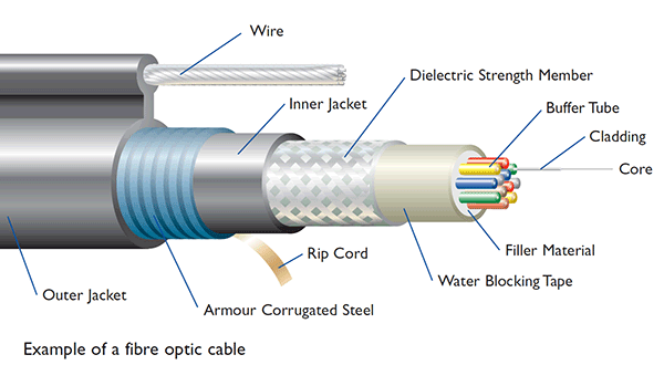
Fibre optic cable is constructed in several layers. The actual glass fibre consists of a central glass core surrounded by a layer called cladding with a different refractive index. This causes light to travel in a controlled path along the entire length of the glass core.
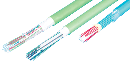
The glass fibre can be placed in a "tight" or "loose" buffer tube array – a protective covering that prevents damage and light escape, often colour-coded for identification. Tight-buffered cable is generally used in horizontal interior installations. Loose buffer tube arrays allow the glass fibre to "float" with considerable movement. As the cable is installed (in conduit, directly buried, or on poles), the glass fibres are not subjected to pulling tension forces and therefore sustain minimal damage or distortion from stretching.
Materials: Glass vs Plastic
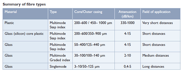
The material used for the core and cladding differs by fibre type. The most common material is glass – extremely pure silicon dioxide (silica). Other types include PCS (Plastic Clad Silica) with a glass core and plastic cladding, or plastic fibre cable with both core and cladding made of plastic.
Glass cable gives the best performance but is more complicated to terminate. Plastic fibre is easier to terminate but offers very short transmission distances – typically 20–50 metres.
Types of Fibre Optic Cable
There are three primary types of fibre optic cables:
Multimode Fibre
A multimode cable has a relatively large diameter core (50 to 400 microns; 62.5 microns is most common) and a total diameter of 125 microns. Multimode cables are available in two categories: graded index and step index.
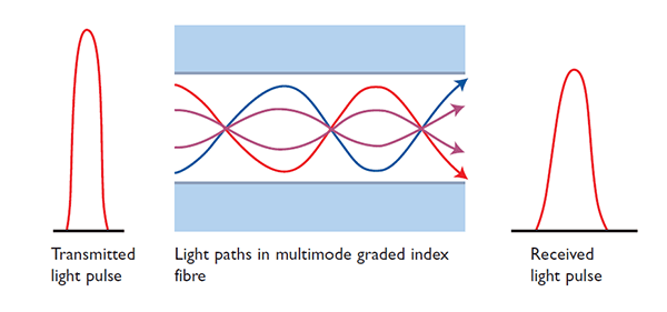
In step index fibre, as modes reflect through the cable, some travel further than others, causing light pulse spread. This results in lower bandwidth. Graded index solves this problem. The refractive index reduces gradually from the core's centre toward the cladding, meaning light beams travel mainly in the cable centre. This delivers higher bandwidth and lower attenuation.
Singlemode Fibre
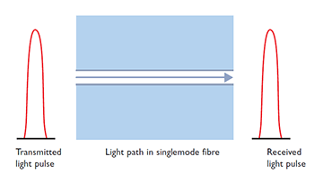
A singlemode cable has a small core (3 to 10 microns; 9 microns is most common) that forces light to follow a more linear single path down the cable, as opposed to the multipath reflections of multimode cables.
Singlemode cable has the highest bandwidth and distance ratings – up to 120 km or more.
Attenuation and Wavelength
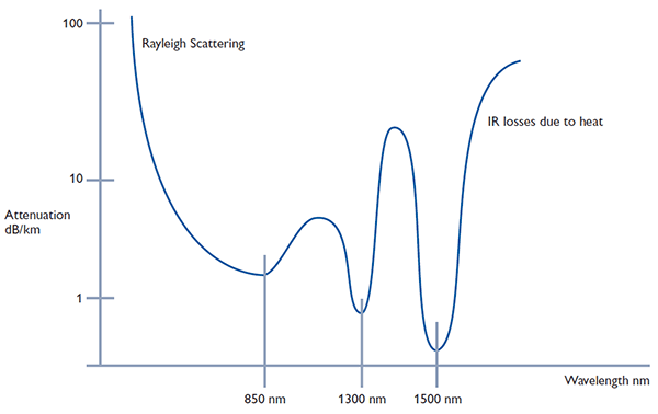
Attenuation in the cable depends on several parameters – wavelength, material, and purity are three important factors.
Attenuation is measured in dB/km and can vary from 0.4 dB/km (singlemode) up to 1000 dB/km (plastic).
Common wavelengths are 650 nm for plastic, 820–1300 nm for multimode, and 1300–1550 nm for singlemode cables.
Transceivers and Connectors
Fibre optic transceivers usually include both a transmitter and a receiver in the same component. These are arranged in parallel so they can operate independently. Both receiver and transmitter have their own circuitry to handle transmissions in both directions.
In practice, Westermo's ODW-series uses SFP transceivers (Small Form-Factor Pluggable), offering flexible configuration. Bi-directional transceivers are also available for full duplex communication on a single fibre using different wavelengths.
Termination and Patch Panels
There are many ways to terminate fibre cables. "Crimp and cleave" involves crimping the connector onto the fibre using special pliers, then carefully cleaving the fibre. A more reliable procedure uses epoxy to bond the fibre into the connector – connectors are available with adhesive already inside. The connector is heated in a special oven for about one minute, the fibre is inserted, and then allowed to cool.
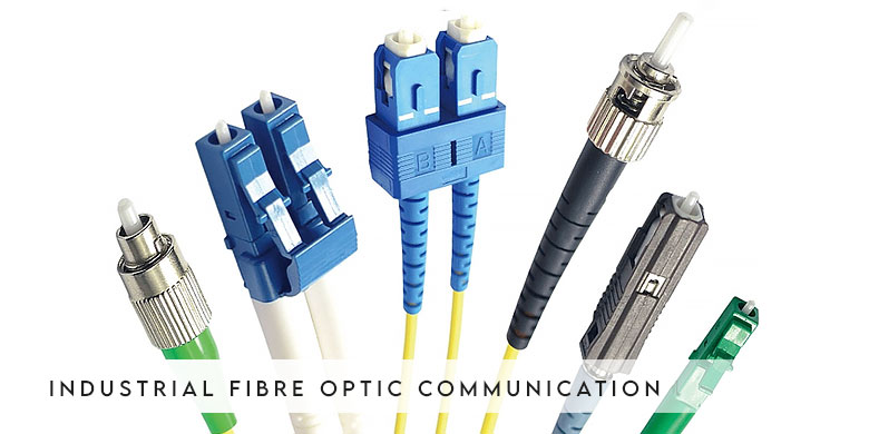
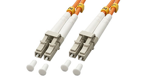
In larger systems, a patch panel is often used at the centre of the installation. A short patch cable connects the patch panel to the fibre optic equipment. The patch cable can be terminated with an ST connector at one end and an LC connector at the other to fit both the patch panel and the fibre optic device.
ST Connector
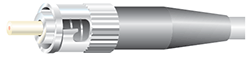
Simplex connector used for single-mode or multimode cables.
LC Connector
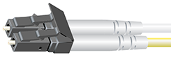
Duplex connector used for single-mode or multimode cables on Westermo's ODW-series.
LC Transceiver (SFP)
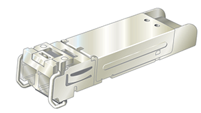
The transceiver used in the ODW-series is an SFP (Small Form-Factor Pluggable), offering flexible configuration. Bi-directional transceivers are available for full duplex on a single fibre.
SC Connector
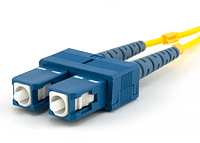
Simplex and duplex connectors used for single-mode or multimode cables.
Bi-directional Transceiver
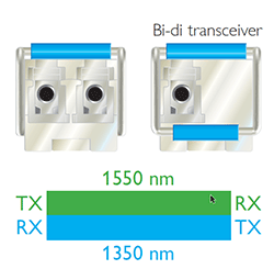
Bi-directional transceivers offer full duplex communication on a single fibre using different wavelengths.
Light Loss in Splices and Connectors
Connector and splice loss is caused by several factors. Loss is minimised when the two fibre cores are identical and perfectly aligned, the connectors or splices are properly finished, and no dirt is present.
Only the light coupled into the receiving fibre's core will propagate. All other light effectively becomes connector or splice loss.

The end finish of the fibre must be properly polished to minimise loss. A rough surface scatters light. Dirt scatters and absorbs light. Since the optical fibre is so small, typical airborne dirt can be a major source of loss.
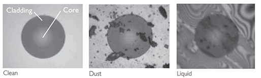
Whenever connectors are not terminated, they should be covered to protect the ferrule end from dirt. Never touch the ferrule end – skin oils cause the fibre to attract dirt. Before connection and testing, clean connectors with lint-free wipes moistened with isopropyl alcohol.
Different Configurations
Fibre Optic Solutions
Fibre solutions are applied where normal copper cable is inadequate – when networks need to extend beyond copper limits, or when heavy industrial environments are not suitable for standard Ethernet or coaxial cable.
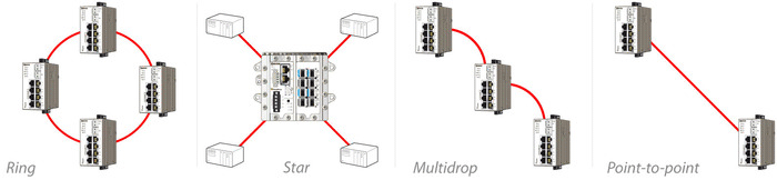
Network Topologies
Extensive fibre ranges allow building any network topology – ring networks with standard STP/RSTP or fast redundancy protocols like FRNT, star networks, multidrop networks, or point-to-point connections. Fibre switches with full management and routing functionality enable simple solutions to complex networking needs.
Certain operators choose Westermo's FRNT (Fast Recovery Network Topology) for sub-50ms recovery in ring networks – a capability that matters when copper cannot reach and fibre is the only option.
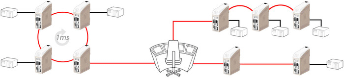
Serial Networks
For serial networks, the ODW-series provides easy-to-install, robust, reliable solutions over fibre optic cable. The ODW-series supports common serial protocols – RS-232, RS-422, RS-485, and PROFIBUS. Models are available for ring, multidrop, and point-to-point networks. In ring networks, reconfiguration times are less than 1 ms in networks with up to 200 devices.
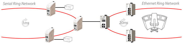
Connect Serial and IP-Based Networks
Fibre product ranges are fully compatible, making it possible to combine serial and Ethernet networks. For applications requiring high availability and resilience, individual ring networks can be combined, allowing hundreds of devices to be connected in a ring with reconfiguration times less than 1 ms.
Credits: Westermo – original technical content adapted with permission.
DESIGN YOUR INDUSTRIAL FIBRE OPTIC NETWORK
Fibre optics eliminate EMI, extend distances, and provide reliable backbones for harsh industrial environments. Throughput advises on fibre optic architectures that perform where copper cannot.
Talk with a Solutions Specialist.
Where is electromagnetic interference compromising your network today – and could fibre solve it?