
The Timing Failure That No Alarm Will Tell You About
Your SCADA says everything is fine. Your protection scheme disagrees. The timing layer is drifting – and no alarm will trigger.

The Silent Fracture
Digital substations depend on sub-microsecond synchronisation. Merging units stream Sampled Values. GOOSE messages carry time-critical commands. Differential protection compares currents that must be perfectly aligned in time.
IEEE 1588 PTP has become the standard for delivering that precision. Under normal conditions, it works.
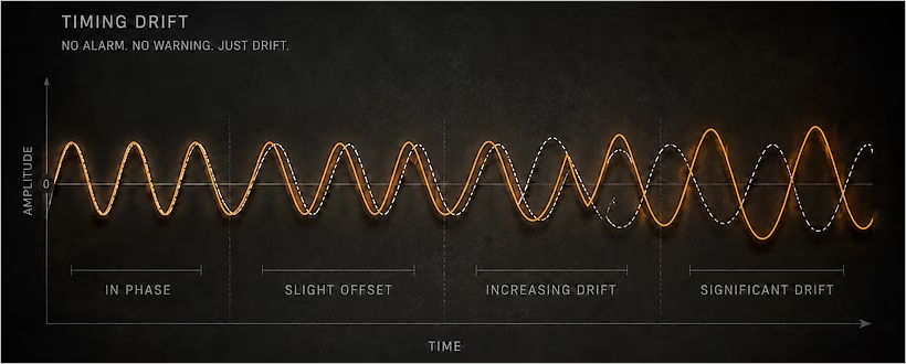
During partial outages, GPS signal loss, network congestion, or grandmaster failover, synchronisation degrades or fractures. Devices may hold over for a short period using internal oscillators, but once that window expires, timestamps drift.
From the outside, everything looks stable – until a fault occurs and protection behaves unexpectedly. False differentials appear. Breakers trip without cause. Or, worse, they fail to trip when they should.
Why The Problem Stays Hidden
The fracture does not always trigger a hard alarm. Clocks can be "close enough" for SCADA but outside tolerance for protection.
By the time engineers investigate, the network has often re-synchronised and the evidence has vanished. Logs show only brief holdover events or minor offset warnings that are easy to dismiss.
The protection misoperation is recorded as "unexplained." The investigation closes. The fault will return.
What to Watch For
Protection misoperations that cannot be explained by fault conditions. Devices that report "holdover" events in logs. Intermittent differential protection alarms that clear before investigation.
These are not random failures. They are symptoms of timing drift.
The Switch's Role in Timing Failure
PTP relies on symmetric path delay. The time a message takes from grandmaster to slave must equal the return path.
When switches introduce asymmetry – different buffer depths on ingress and egress ports – the slave calculates the wrong offset. The clock drifts.
Standard Ethernet switches are not designed for PTP. They add jitter. They drop timing messages. They cause fractures.
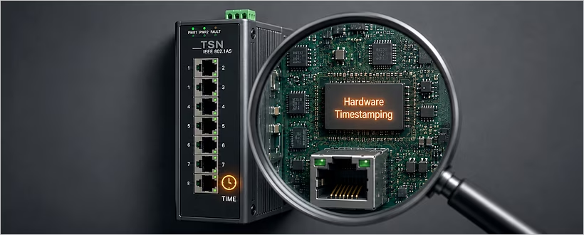
Industrial switches designed for PTP use hardware timestamping at the physical layer. Consistent delay through the switch. Support for transparent clock and boundary clock modes.
Where ATOP Fits
Timing failures are not only about switches. They are also about the physical layer. ATOP provides rugged media converters and serial-to-Ethernet gateways that maintain signal integrity across long distances and harsh environments.
When timing messages travel over copper in high-EMI environments – substations, rail corridors, industrial yards – signal degradation can introduce jitter. ATOP's fibre optic converters eliminate EMI, ensuring that PTP messages arrive with consistent delay.
ATOP's industrial-grade devices are certified for IEC 61850-3 substation environments. They are designed to operate where commercial equipment fails – wide temperatures, electrical noise, vibration. The physical layer matters for timing. ATOP secures it.
Where Westermo Fits
Westermo builds switches designed for PTP. Hardware timestamping at the physical layer. Consistent delay through the switch. Support for transparent clock and boundary clock modes.
Interestingly, Westermo's PTP implementation includes holdover validation. The switch monitors its own clock drift when external synchronisation is lost. If drift exceeds tolerance, it raises an alarm – before protection misoperates.
The difference is not visible in normal operation. It becomes visible when the network is under load – when timing matters most.
What You Can Do Now
You do not need to deploy new timing infrastructure today. You do need to validate what you have.
During a scheduled maintenance window, remove your primary grandmaster for ten minutes. Monitor every PTP slave. The devices that lose synchronisation completely are your risk points.
Check your switch configuration. Are PTP transparent clock features enabled? Is holdover validation active? Are alarms configured for timing drift?
Review protection misoperation logs. Look for events marked "unexplained." Ask whether timing could have been the cause.
The Bottom Line
Precision timing is assumed until it fractures. By then, protection has already misoperated.
The logs show nothing. The network re-synchronised. The evidence vanished.
Validate before the fault, not after.
VALIDATE YOUR SUBSTATION TIMING UNDER STRESS
Throughput advises on PTP timing architectures that include holdover validation, transparent clock configuration, and alarm management for timing drift.
Talk with a Solutions Specialist.
When did you last test your substation's timing under stress – and what did you find?