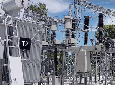
Electric Power Systems
Networking for substation communications, protection systems, IEC 61850 architectures, and grid edge integration with deterministic timing requirements.
Safety-critical utility networks operate where failure consequences include catastrophic events – requiring deterministic performance verified through rigorous processes, physical separation to prevent common cause failures, and cybersecurity that protects without compromising safety functions, all within regulatory frameworks that mandate demonstrable rather than assumed reliability.

Safety-critical networks require verified deterministic performance under all foreseeable conditions – not just typical operation – with failure modes analysed, quantified, and mitigated through design rather than discovered during incidents.
In conventional industrial networks, occasional packet loss or delayed delivery may cause process inefficiencies or temporary outages. In safety-critical applications, such events could prevent safety system activation or cause spurious operation, with potentially catastrophic consequences. The design approach therefore differs fundamentally: instead of optimising for average performance, safety-critical networks guarantee maximum latency, minimum throughput, and availability under defined fault conditions. Every component – cables, connectors, switches, power supplies – must have quantified failure rates and documented performance under stress conditions including seismic events, electromagnetic interference (EMI), and loss of cooling.
The safety lifecycle defined in IEC 61508 and IEC 61511 governs network design: hazard and risk analysis identifies safety functions; safety integrity level (SIL) assignment determines performance requirements; design implements necessary risk reduction; and verification confirms requirements are met. Networks become part of the safety instrumented system (SIS), requiring the same rigour as sensors and final elements. Documentation is extensive – every design decision, component selection, configuration parameter, and test result must be traceable throughout the system lifecycle. The regulatory environment adds another layer: nuclear facilities require licensing basis compliance, while other safety-critical utilities follow sector-specific regulations that may reference international standards.

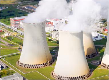
Nuclear safety systems require networks with deterministic performance, physical separation between redundant trains, and defence-in-depth security to protect critical protection functions.
Nuclear reactor protection systems and other safety-critical networks require deterministic performance with guaranteed maximum latency, physical separation between redundant trains, and cybersecurity that prevents unauthorised access while maintaining safety function availability.
Nuclear safety systems are typically designed with multiple redundant trains (usually 2–4) that must operate independently – a failure in one train should not affect others. Network design implements this independence through physical separation: separate cable routes, separate equipment rooms, separate power supplies, and often separate communication technologies between trains. Within each train, the network must deliver protection signals with deterministic timing – reactor trip signals typically require delivery within 50–100 milliseconds from sensor to actuation, including all processing and communication delays.
Network architecture follows defence-in-depth principles: multiple layers of protection with diverse technologies. For example, hardwired signals may provide the ultimate protection layer, with networked systems providing additional layers. Time-critical communications often use dedicated networks rather than shared infrastructure. Quality of service (QoS) mechanisms alone are insufficient; traffic analysis must prove that worst-case latency meets requirements even during fault conditions when other systems may generate high traffic. Equipment qualification ensures components survive design basis events including seismic activity, loss of cooling, and high radiation levels. Cybersecurity measures must protect against threats without compromising safety function availability – safety systems cannot be taken offline for security updates during normal operation.
The IEC 61508 (functional safety of electrical/electronic/programmable electronic systems) and IEC 61511 (process industry sector) standards provide frameworks for safety lifecycle management that apply to networks carrying safety functions.
IEC 61508 takes a hazard-based approach: identify hazardous events, determine risk, assign safety integrity levels (SIL 1–4), design systems to achieve necessary risk reduction, and verify performance. Networks carrying safety functions become safety-related systems requiring the same rigour as other components. SIL assignment considers both systematic and random failures: systematic failures (design errors, software bugs) are prevented through development processes; random failures (component wear-out, environmental stress) are quantified through reliability analysis.
Network design for IEC 61508 compliance includes several specific requirements: failure mode and effects analysis (FMEA) for network components, diagnostic coverage analysis to detect failures, common cause failure analysis to identify dependencies, and proven-in-use arguments for commercial off-the-shelf (COTS) equipment. Safety manuals from equipment suppliers provide failure rate data and diagnostic capabilities. Network architectures often include redundancy with voting logic – 2-out-of-3 or 2-out-of-4 configurations that tolerate single failures. The entire safety lifecycle must be documented, with change control procedures ensuring modifications don't inadvertently affect safety performance. Independent assessment by certified functional safety experts validates compliance before system commissioning.
Reactor protection systems require networks that guarantee signal delivery within strict time bounds under all plant conditions – including design basis accidents when multiple systems activate simultaneously.
When reactor parameters exceed safe limits (high pressure, high temperature, low coolant flow), protection systems must initiate appropriate responses within defined timeframes. Network delays directly affect response time, potentially allowing conditions to worsen beyond design basis. Deterministic networking ensures maximum latency bounds are never exceeded, even during worst-case traffic conditions. This requires more than just prioritisation – it requires traffic scheduling that reserves bandwidth for safety messages and prevents lower-priority traffic from causing congestion.
Implementation approaches include time-triggered networks that schedule communications in fixed time slots, or rate-constrained networks with enforced bandwidth limits. Traffic shaping at network edges prevents devices from overwhelming the network. Performance verification uses network calculus or similar methods to prove worst-case latency bounds. Testing under simulated accident conditions validates performance when multiple systems generate alarm and control traffic simultaneously. Redundancy with diverse technologies provides additional assurance – for example, fibre optic primary with hardwired backup. Clock synchronisation via precision time protocol (PTP) with hardware timestamping ensures accurate event sequencing across the protection system. Equipment from partners like Westermo that offers deterministic Ethernet capabilities can form part of such safety-critical architectures when properly qualified and integrated.
Safety-critical networks implement physical separation between redundant trains and technological diversity to prevent common cause failures from affecting multiple safety systems simultaneously.
Physical separation prevents common cause failures from affecting multiple safety trains, while technological diversity provides defence against design errors or common mode failures that could affect identical redundant systems.
Identical redundant systems may share common failure modes – a software bug, manufacturing defect, or environmental stress could affect all copies simultaneously. Physical separation addresses some common causes: separate cable routes prevent a single fire or physical damage from affecting multiple trains; separate equipment rooms provide fire separation and environmental independence; separate power supplies prevent single electrical faults from disabling redundancy. Technological diversity takes this further: different manufacturers' equipment, different communication protocols, or different network topologies between trains.
Implementation considers practical constraints: diverse technologies increase maintenance complexity and spare parts inventory. The balance depends on safety analysis – higher safety integrity levels (SIL 3–4) typically require more diversity than lower levels (SIL 1–2). Physical separation requirements include minimum distances between cable trays, fire-rated barriers, and diverse entry points into buildings. For nuclear facilities, separation must also consider design basis events like earthquakes – cables and equipment in different trains should not be mounted on the same structures that could fail together. Documentation of separation must be maintained throughout the facility lifecycle, with change control procedures ensuring modifications don't compromise separation.
Nuclear instrumentation and control (I&C) system cybersecurity must protect against cyber threats while maintaining safety function availability – a balance requiring defence-in-depth approaches that don't create single points of failure in protection systems.
Nuclear facilities face cyber threats ranging from generic malware to targeted attacks. Safety systems present particular challenges: they cannot be taken offline for patching during normal operation, they often include legacy equipment with limited security features, and security measures must not interfere with safety function timing or availability. The approach follows defence-in-depth: multiple layers of protection so that a breach at one layer doesn't compromise the entire system.
Implementation starts with network segmentation following the utilities core guidance: safety systems on separate networks from administrative systems, with controlled gateways for necessary data exchange. Air gaps provide the strongest separation but are increasingly impractical for modern facilities that need data for monitoring and optimisation. Instead, unidirectional gateways or data diodes allow safety system data to flow out while preventing any inbound communication. Secure remote access for maintenance uses zero-trust principles with multi-factor authentication and session monitoring. Intrusion detection systems monitor for anomalies in safety network traffic patterns. Importantly, cybersecurity measures undergo the same safety analysis as other modifications – they must not adversely affect safety system performance or reliability. Regulatory oversight ensures cybersecurity programmes meet nuclear-specific requirements.
Maintenance and testing networks support periodic safety system verification without interfering with operational systems, requiring careful design to prevent test activities from affecting plant safety or creating cybersecurity vulnerabilities.
Nuclear safety systems require periodic testing to verify continued functionality. Some tests can be performed online, while others require taking equipment out of service. Test networks connect test equipment to safety systems, creating potential pathways for interference or cyber intrusion. Design must ensure test activities cannot inadvertently affect operational systems, and test networks cannot become entry points for malicious actors.
Implementation typically uses physically separate test networks with interlocked connections to operational systems. Test connections may use changeover switches that physically disconnect operational paths when test connections are active. Test equipment undergoes the same cybersecurity controls as operational equipment. Test procedures include verification that normal operation is restored after testing. For online testing, the network must accommodate test traffic without affecting safety system performance – dedicated bandwidth reservation or test windows during low-activity periods. Documentation of test network configuration and procedures is essential for regulatory compliance. Secure remote access solutions from partners like Secomea can enable authorised test personnel to connect to test networks without exposing them to broader threats.
Throughput Technologies advises on nuclear and safety-critical utility networking that meets rigorous regulatory requirements while providing deterministic performance for protection systems, implemented through processes that verify rather than assume reliability.
Talk with a Solutions Specialist to discuss safety-critical network design for your utility applications.
Nuclear safety systems typically require SIL 3 or SIL 4, depending on the consequence of failure. Reactor protection systems generally require SIL 4 – the highest level – with risk reduction factors of 10,000–100,000. Support systems may require SIL 2 or SIL 3. The specific SIL assignment comes from probabilistic safety assessment (PSA) that quantifies risk and determines necessary risk reduction. Network design must then achieve the required SIL through appropriate architecture (redundancy, diagnostics), component selection (qualified equipment with known failure rates), and implementation (verified design processes). SIL certification of network equipment helps but doesn't guarantee system SIL – the entire safety loop including sensors, logic solvers, networks, and actuators must be evaluated together.
Verification combines analysis, testing, and monitoring. Analysis uses network calculus or similar methods to prove worst-case latency bounds based on traffic patterns, switch forwarding delays, and link capacities. Testing under worst-case conditions validates the analysis – generate maximum traffic from all devices simultaneously while measuring latency for safety messages. Long-term monitoring during operation confirms performance maintains within bounds. The verification must consider all operational modes: normal, transient, accident, and test conditions. Equipment characteristics must be known – commercial switches with variable latency due to store-and-forward mechanisms may be unsuitable; cut-through switches with fixed latency may be required. Documentation of verification activities is essential for regulatory compliance and safety case submission.
Separation requirements depend on the hazard being protected against. For fire separation, cables in different safety trains typically require at least 6 metres horizontal separation or 1-hour fire-rated barriers. For seismic events, equipment and cables should be mounted on different structural elements that won't fail simultaneously. For flooding, equipment in different trains should be at different elevations or in separate waterproof compartments. Specific requirements come from the facility's design basis and regulatory guidance. Documentation of separation is critical – cable routing drawings, equipment location records, and barrier specifications must be maintained throughout the facility lifecycle. Change control procedures ensure modifications don't compromise separation – a seemingly minor cable rerouting could inadvertently reduce separation below requirements.
Implement defence-in-depth with safety as the overriding priority. Start with physical security – prevent unauthorised physical access to safety systems. Implement network segmentation that separates safety systems from other networks, with unidirectional data flow out of safety networks where possible. Use application-layer security that doesn't affect network timing – for example, message authentication codes rather than full encryption if timing is critical. Schedule security updates during planned outages rather than during normal operation. Conduct security assessments that include safety personnel to ensure security measures don't compromise safety functions. Most importantly, integrate cybersecurity into the safety lifecycle – security requirements should be identified during hazard analysis and addressed throughout design, implementation, and operation rather than added as an afterthought.
Extensive documentation throughout the safety lifecycle: hazard and risk analysis records, safety requirements specifications, architecture descriptions, failure mode and effects analyses, reliability calculations, design verification reports, installation records, commissioning test results, operational procedures, maintenance records, modification records, and periodic review reports. Each document must be version-controlled, with traceability from requirements through implementation to verification. Regulatory submissions typically include safety cases that compile this evidence to demonstrate compliance. The documentation burden is significant but necessary – in safety-critical applications, if it isn't documented, it effectively didn't happen from a regulatory perspective. Electronic document management systems with appropriate access controls and audit trails help manage this documentation throughout the facility lifecycle.
Networking for substation communications, protection systems, IEC 61850 architectures, and grid edge integration with deterministic timing requirements.
Networking for pipeline SCADA, leak detection, compressor station control, and long-distance communications along pipeline corridors with appropriate redundancy and security.
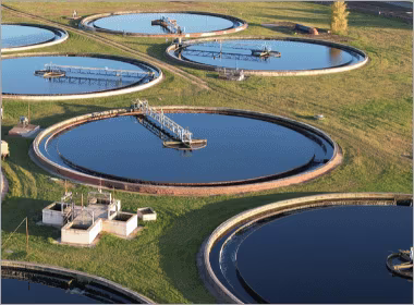
Network design for water treatment plants, distribution monitoring, pump station control, and wastewater management with reliability requirements for continuous public health protection.